
Author: Matt Webb
Date: 10/05/2005
Subject: Fiat 124, Retrofitting
a Bosch Alternator.
Resources: Mirafiori members
and first hand experience.
Introduction to 124
alternators:
Later 124s came with an internally regulated Bosch alternator installed on the intake side of the motor. Earlier cars were equipped with Marelli alternators. For some it is desirable to convert to the Bosch unit. From my experience they are very reliable. Support is also very good for the Bosch alternators. In most cases, they can be rebuilt locally.
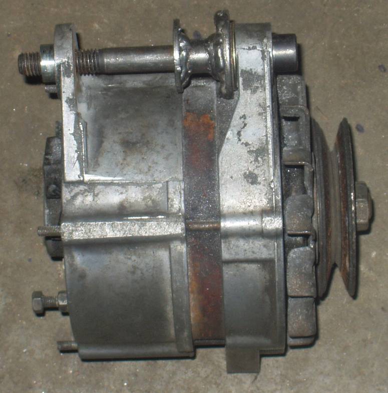
The Bosch alternators referred to in this document are 55A units, and their part numbers are known to vary somewhat, but physical characteristics stayed the same. My understanding is that the later 65A units are interchangeable. I have two 55A units, with different part numbers but the same physical dimensions. They are:
- Bosch 0 120 489 641 642
- Bosch 0 120 489 742 743
Mounting the Bosch on the
Intake Side:
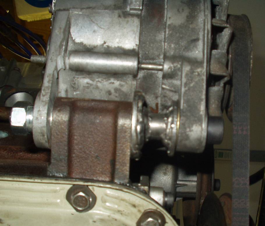
The Bosch unit always came installed on the intake side of the engine. This is achieved with the correct oil filter mount, which has a large boss in it for the large lower alternator mount bolt. Also required is the upper bracket, a long bent and arched slotted piece of steel. This bracket allows adjustment of belt tension. It is fastened to the alternator with a single bolt (alternator holds a captive nut), and attaches to the block via a large stud. This will prove to be a major hurdle for cars with block mounted distributors, and may be impossible. Fabrication and time would certainly be a requirement.
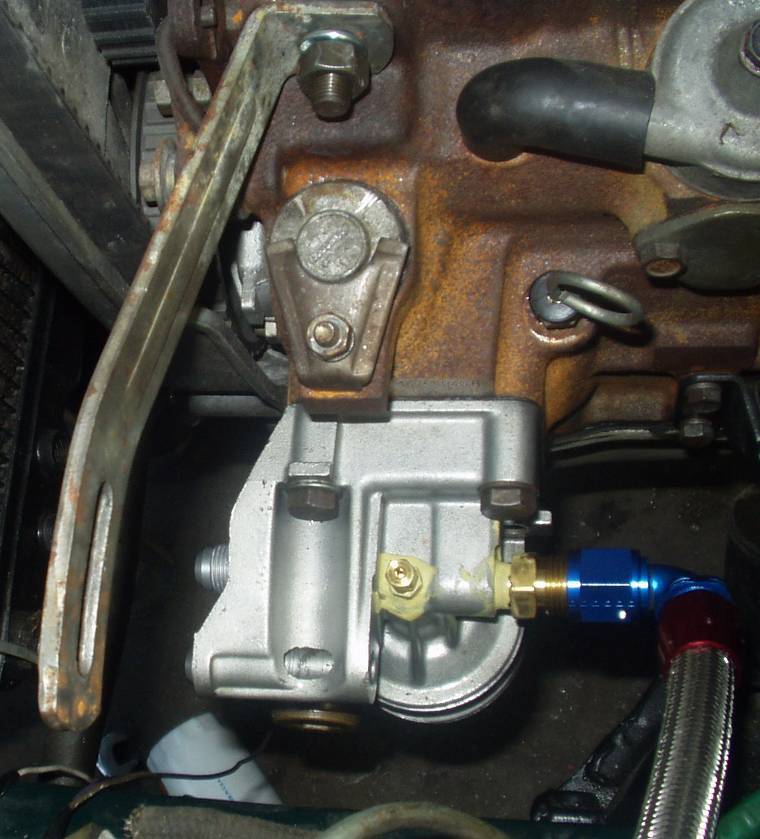
This picture shows the correct upper mount and correct oil filter housing mount.
Ignore the brass fitting on the top of the oil filter housing, this is not stock and would interfere with the alternator if mounted here.
The Block Stud:
In some cases the block stud is not a stud at all, it is sometimes a bolt that screws into shallow threads in the block. In the case of the stud, the threads penetrate the block and reach the water jacket around cylinder number one.
If your block does not have the stud or threaded hole in place already, you will need to add it. The shallow threads that go along with the bolt version have been reported to pull out easily upon torque up, so it is advised that you source the correct stud.
Sorry I didn't make proper measurements, but ball park measurements for the stud are 25mm threads for the block side, 5-7mm shoulder, and 25mm threads for the bracket side. Thread pitch is 12mmx1.25mm
It is feasible to salvage a stud from another block. That's what I did. You will need two 12mmx1.25mm nuts, some penetrating oil, and a mapp gas torch to remove it.
Drilling and Tapping:
The area you'll be drilling and tapping is clearly visible on the block. It is a flat square bulge that sticks out on the block. It is located directly above the block mount distributor hole.
The hole is to be drilled more or less dead center of this bulge. It is, however, highly recommended that you mock up the alternator install and find where the upper mount will land, scribe the hole on the block and drill where you've marked.
For blocks on the stand, this is easy. For engines installed in the car, this is tricky. Fitting a drill and drill bit is hard to do. A right angle drill will help, but not solve the clearance issue unless you raise the engine. But really you don't want to raise the engine, you want to rotate the engine so that the intake side pivots upward. To do this you'll want to loosen the exhaust and the exhaust side motor mount. Remove the intake side motor mount nut. Place a jack under the engine, and use a block of wood on the jack to raise the intake side of the engine. Raise it until it refuses to go anymore. I got mine raised enough to drill with an 18v DeWalt and a full length bit.
Start with a small bit and work your way up. This helps a lot. Cast can be a bear to drill, especially with a large bit. Starting with a small pilot is very helpful. This method also allows you to gradually correct for a crooked hole. The target hole size is 31/64. You can get away with using a 15/32” drill bit. While drilling, hold a shop vac at the hole. This way, when you penetrate the block, shavings to enter the water jacket are kept to a minimum. For those who are really concerned with this, all you have to do is close off your cooling system and add compressed air. When you penetrate, the shavings will be flushed out.
Now you can tap the hole. With cast iron, you DO NOT want to use a lubricant while tapping. Tap dry. Use the shop vac and take your time. Tap it all the way through.
Clean the threads of the stud, coat the block threads and stud threads with Loctite. Put two nuts on the stud and tighten them well. Use the nuts to install the stud and torque it down well. Let it dry, and later use care to remove the nuts without backing out the stud. This will ensure that coolant will not weep from the hole.
And here we can see the
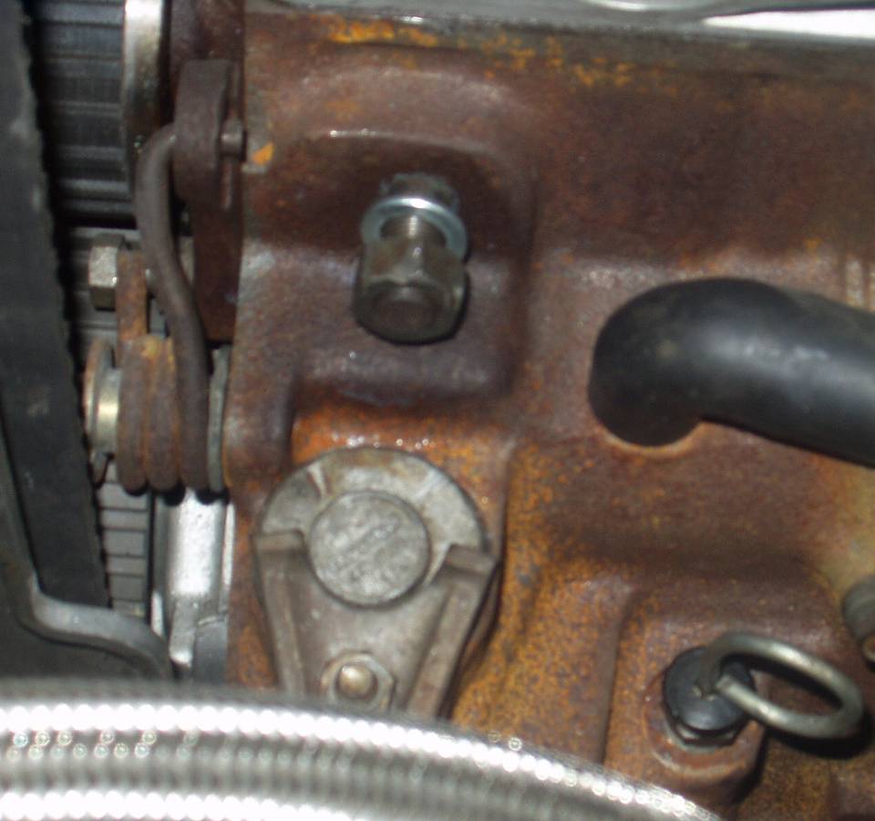 stud
for the upper mount.
stud
for the upper mount.
Pulleys:
Pulley offset can vary, and you may find that you will have to swap to later style water pump and pulley, and a later style crank pulley. It's either this or you have to modify the alternator offset to match.
Mounting the Bosch on the
Exhaust Side:
This is a little bit tricky and requires fabrication work. I only have experience with doing this on the blocks that have a cast in ear on the bottom front of the exhaust side of the block. There are other blocks that have two studs there instead and I suspect that bracketry is available for these to run Marelli alternators.
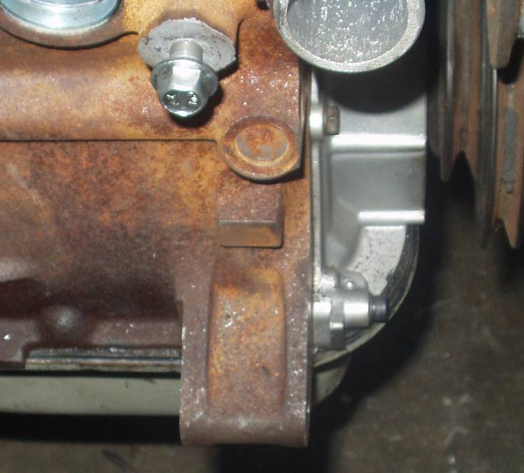
The lower ear on the exhaust side of the block. The bolt at the top is for the upper mount. Some blocks have two studs instead of the ear. Note that the ear is hollow and waiting for a bolt.
The Lower Mount:
Step one is to mount the alternator to the lower mount. Before doing so, press the bushing in the back side of the alternator so that it sits flush with the inside surface of the alternator mount ear. Slide the alternator as far forward as it will go. Notice how it doesn't line up with the other pulleys? This will need to be addressed.
Make measurements and write them down. The goal is to find out how much further forward the alternator needs to go. In order to do this, material must be removed from the rear alternator mount. In my case, 3mm was needed. I added 1mm or so to provide adjustment, so in total I needed to remove 4mm. Some thin shim washers can be used in the end to fine tune it.
The next step is to come up with the extra space. This is achieved by chucking the alternator up in the vice, and taking a hack saw to it. You need to remove material from the inside face of the rear alternator mount ear.
Another option is to remove some material from the alternator, and to add height to the pulley by shimming it with washers. 2mm is the maximum you can gain with under pulley shims. I originally went this route but then decided against it. If I take this thing in to an alternator shop to get rebuilt it's going to be hard enough to get the same modified case back, let alone maintain custom pulley shimming.
I debated over how to cut the alternator down for quite some time, worried about getting a square cut. I came up with a method that worked quite well. Cut off, with the hacksaw, the amount you need minus about 2mm. Take your time, get a square cut. Install the bushing so that its surface rests at the desired height. It should be recessed about 2mm down in the hole.
Remove the remaining material with an angle grinder and a cutoff wheel. Use the cutoff wheel as a grinder, not a cutter. Take your time and constantly check for a square surface. You'll know when you reach the bushing, as you'll see sparks. Stop and check. You can see how square your cut is by looking at the grind marks on the bushing. Compensate grinding angle and recheck until you've achieved even grinding marks around the perimeter of the bushing. You'll be left with a nice square cut.
This, in my opinion, is the cleanest approach with hand tools. Another thought is this. The bushing is what squares the alternator up on that side in the stock configuration, so you can cut the alternator well beyond what you need and not have to worry about a square cut. Let the bushing take care of it.
This shot shows an unmodified alternator (bottom) as compared to the modified alternator (above). The bushing has also been cut down. Nice how that casting mark is just about the perfect line to use as a cutting guide.
Now that that is done, you'll be left with a large void between the block ear and front alternator ear. I filled mine with a hollow tube with washers welded the end. Stacked washers would work too. Whatever the direction you take, a square spacer is key. My spacer came out to be 26.5mm, and with an additional 0.75mm shim washer, pulley alignment came out perfect.
 This
picture shows the modified alternator with bolt and required spacer. Appx 27mm
worth of spacer is required. Lots of stacked washers could also be used.
This
picture shows the modified alternator with bolt and required spacer. Appx 27mm
worth of spacer is required. Lots of stacked washers could also be used.
A square spacer is key to proper pulley angle.
 This
shot is from under the car. It shows the modified alternator mounted in place
with spacers.
This
shot is from under the car. It shows the modified alternator mounted in place
with spacers.
Measurements consolidated into one area –
- Block Ear (lower mount) = 47mm wide
- Stock Alternator inside spacing = 71mm
- Modified Alternator spacing = 75mm
- Front spacer = 27.25mm total
-
Remaining 0.75mm taken up by rear alt bushing.
The Upper Bracket:
This conversion will require the upper bracket from a Marelli alternator setup. This bracket bolts to the block with one bolt, with the hole at the front of the block and below the heater pipe. This bracket will require grinding, cutting, and welding.
The first step here is to mount the upper bracket and make some measurements. You will have to re-drill the mount hole to get it better into the ball park to work with the Bosch alternator.
Next step is to deal with how the mount interferes with one of the alternator case bolts. Grinding will correct the clearance issue. This will take a few tries.
The final step is to modify the adjustment arc. It appears that the arc of the Bosch alternator is different than that of the Marelli. I tried marking and grinding all surfaces, and after a lot of frustration that just didn't seem to lead anywhere. Here's the solution:
Cut the end of the bracket with a cutoff wheel. Cut from the end into the inner adjustment arc, effectively splitting that end of the bracket. Mount it to the block and to the alternator. Pull the alternator back while prying the split bracket apart with a pry bar / screwdriver. Spread the split bracket until you get free adjustment of the alternator.
Remove the bracket and fill the now large gap at the end with some creative welding. Grind it smooth and bolt it up.
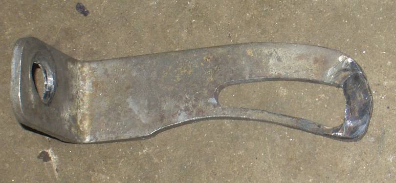
The modified upper mount. Looks like a lobster claw to me. YUM.
I have concerns about how thin the lower edge came out. Those mods were more aggressive than needed. Hindsight is always 20/20.
Wrap the pulleys with some rope and measure to determine belt size. Personally, I wanted a tight fit. This will give you best thermostat / coolant hose clearance. It's also nice for a high RPM application where belt stretch is a concern. The belt I ended up with was a Gates #7335.
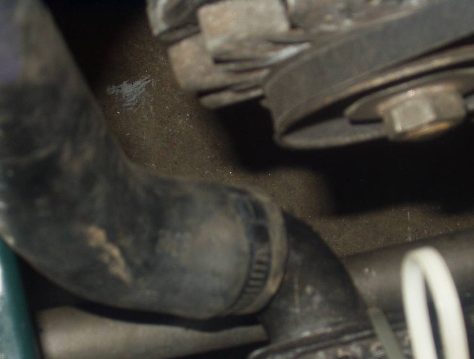
This shot clearly shows how much clearance there is between the alternator pulley/fan and the lower radiator hose.
It's tight, but not an issue. The external thermostat clears the alternator without problems.
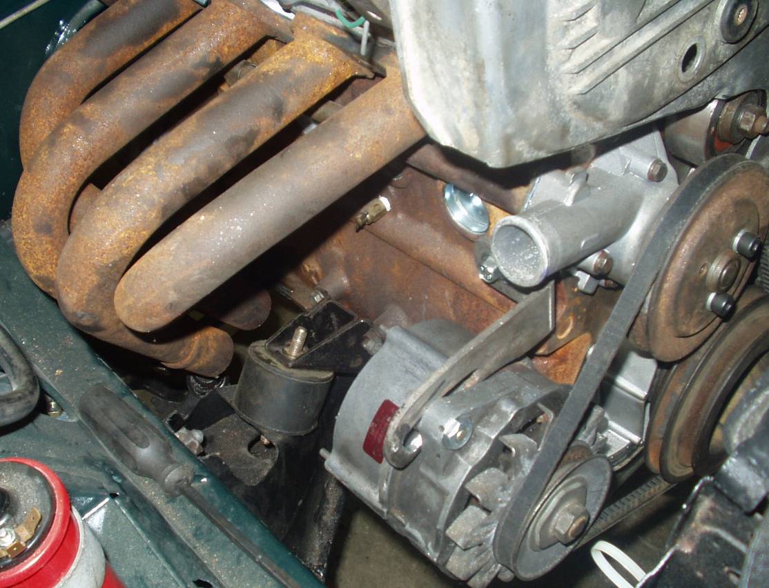
Here is the alternator installed with a popular aftermarket 4-2-1 header. No problem with clearance. Heat could pose a problem.
Wiring the Bosch:
I Don't know much on the subject when it comes to converting from a Marelli setup. There are three things to consider, and none of them are hard.
- Proper grounding of the alternator (usually just done through the block)
- Alternator output. Heavy gauge wire that goes directly to the battery cable + post on the starter
- Small wire for dash battery charge light