Mira Logo
FAQ

Project.
FIAT ELECTRICAL
RESTORATION
by
James Seabolt
updated 05/30/05


Why do Fiats have so many electrical problems? What if I told you that you could eliminate virtually all problems, prevent future problems, and get your electrical system in almost "like new condition" all in one day? The reason Fiats suffer from so many problems is because of the electrical terminals, not the wiring. It's not nessessary to replace any of the existing wiring nor is it nessessary to replace every terminal on the car. Just the ones in the problem areas.

These procedures are centered around the 79+ Spider 2000s and X 1/9s but these methods can be applied to any year or model.

NOTE: I take no responsibilty for negligence! If you do something to your car and your electrical system catches fire, don't email me! I actually recieved an email from a guy who installed some headlight relays and then emails me and says smoke started coming out from the behind the dashboard. Needless to say I never replied. How and I supposed to know what this guy did? See precautions below.

What causes this:
Poor plating is the reason. Over the years, humidity slowly penetrates the plating material and gets into the steel terminals/bulb sockets. This rust/corrosion acts as a resistor. This restricts current and causes a voltage drop. Fiats seem to be the exception for some reason. The wiring on my 68 Fairlane looks far worse and I've done practically nothing to it and it still works perfectly.

Main problems:
Dim headlights
Slow windshield wipers
Slow or non functioning park/turn signal lights
Starter problems

These are where most of the problems crop up. Mainly because the ground connectors used for these circuits are within the engine compartment and are not protected from the weather. Also the tailight sockets are vulnerable because the gaskets leak and allow water to gather on the sockets.

Precautions:
Always disconnect the NEGATIVE cabel from the battery before working on the electrical system.
Always use the correct guage wire.
Always install a fuse rated for the wire used to operate the component.
Always wear saftey glasses when working around acids (you see later) and stripping wires.

Basic Tools/equipment:
It's not nessessary to go out and buy a whole arsenal of tools for this project. I have amassed most of these tools over the years.
Digitial multimeter (get a digital not analog).
Test light.
Wire stripper (cheap pair from Auto-Zone will do).
High quality crimper (don't use the above tool for the purpose).
Drill.
Pop rivet gun
Assorted electrical terminals.
New assorted nuts and bolts.
Electrical grease: I prefer Truck-Lite (from IAP). Kopr shield is another (from Eastwood and Co).
Small brass bristled brush.
Various grit sandpaper.
Wiring diagram for your model. (see below for 124 Spiders)

Before starting:
If your not experiencing any dead batteries, you could skip this step but it's a good idea to have the alternator checked anyway. Most rebuilders will do it for free. A good alternator should produce a voltage of at least 14 volts. The current will vary depending on what year your car is. It's also a good idea to check for a loose or worn V-belt and top up the battery will distilled water. If you notice the battery is swollen (caused by water that has evaporated) replace it.

Techniques:
After cutting off the old connector and stripping back the wire, If the copper wire looks shiny, you could go ahead and install a new terminal. But if it looks black, green or otherwise, it must be cleaned to ensure good contact with the new connector. My method is to strip the wire back about 1/2" and then spread the strands apart so they are not touching one another. Then I swirl the wire in a bottle of acid. Just about any kind of acid will work (but not sulfuric!!). I have been using an acid specifically used for cleaning copper. I can't remember the name right off hand but it's in a black bottle and is sold at K-Mart.

Once the wire is clean and shiny, swirl the wire in a cup of water then wipe dry with a towel. Then twist the strands of wires back together.

Installing a terminal:
This next step may seem trival, but for a long time I had been doing this the wrong way. If the wire is already stripped, cut the strands off so that about 1/4" is visible from the insulation. Just enough so the strands will slide into the connector. Most connecters except for butt connectors, have a small slot in the metal sleeve where the wire is inserted. When crimping the connector, place the curved side of the jaws of the crimper on this side. The toothed side goes on the side of the connector where there is no slot. Butt connectors have no slot, so this does not matter.

Primary connections:
Start with cleaning the battery connectors. There is a small circular brush made specifically for this purpose. Replace the bolt that holds the negative battery cabel to the chassis and coat the new bolt with Kopr shield. I checked the resistance of an old negative battery I took from my 81 Spider and it measured .1 ohms which is perfect. The battery post connectors are sealed well and should not require replacing unless the wires are separating from the connectors.

Then goto the starter. On most models you will find three connectors at the main post. One is big thick cabel with green insulation. This cabel leads to the positive post of the battery. I wouldn't worry too much about this connector since it is usually in good shape. But if the connector is corroded, replace it. Then you should find a thick brown wire and a thick red wire behind it. One wire leads to the alternator and the other wire leads to the ignition switch. Install new terminals on those two wires and at the other end of the wire going to the alternator. It's also a good idea to install a new connector on the small red wire going to the starter solenoid.

Grounds:
At some point in time, Fiat consolidated the grounds. These grounds are connected to a main "pod" as I like to call it. These pods are located behind the headlights on the inner fenders on the 2000 Spiders. NOTE: some 1978 124 Spiders have these pods. On later X 1/9s, these pods are located within the headlight motor compartments and there is an extra pod located on the driver's side in the engine compartment. There is also an extra pod located under the dash (both models) but these are usually OK since the are shielded from the weather. I'm not sure if 131/Bravas or Stradas have these pods, but I imagine they do.

The best method of restoring these is to sandblast and replate them. I use a zinc alloy electroplating kit I bought from Eastwood and Company. The kit sells for about $65 so if don't feel like it's a good investment, you can hire this work out by an electroplater. Just about any metal used to plate steel is acceptable. Chrome, gold, zinc alloy, etc. are all good conductors.

If you use the Eastwood kit, you'll notice that afterwards the metal has a white layer of junk on it. This can be removed with #0000 fine steel wool. After the pods are restored and the wires/connectors have been taken care of, coat the pods and connectors with Truk lite or a similiar grease.

Whenever you find a ground stud, clean it with a brass brush and coat it with Kopr shield and install a new nut. Whenever you find a bolt, replace it and coat it with Kopr Shield.

I prefer to use Truk lite on newly plated connections but anywhere a bolt or stud is used, I like to coat it with Kopr shield. Truk lite is not as good but is not as messy. But Kopr shield can use used anywhere if you can live with the mess and is very good for protecting bare steel. Copper based antiseize compound can be substitued for Kopr shield.

The final method is to replace the pods. I spoke with Ed at Caribou imports and he says he has new pods in stock.

When it comes to earlier models, you will find that the grounds run everywhere and are connected to ring terminals secured to the chassis with a bolt, stud/nut or screw. The best way to take care of these type grounds are to install new ring terminals and create a new connection to the chassis. Drill a hole and secure the wire with a ring terminal to the chassis with a sheet metal screw. You may have to extend the wire . If so use the same guage wire with a butt connector. Also be sure to use the Kopr shield on the screws.

Check that the ground cabel which goes from the chassis to the bell housing on the transmission (all models) is not broken. If you don't mind spending a few bucks, go ahead and replace it along with the bolts.

Some people like to run an extra 10 AWG wire from somewhere on the engine like the fuelpump block off plate to the chassis. I never found this to be nessessary but any extra engine ground cannot hurt.

Tailight sockets
You will probably find that the lower bulb holders will be quite rusty. These are held onto the cards by pop rivets. Begin by drilling out the pop rivets that secure the bulb holders to the cards. I know on the 2000 Spiders, the tailight cards have a rear cover which are also secured with pop rivets which must be drilled out before the bulb holders can be removed. Early Spiders and X 1/9s are a bit different but same method applies.

After installing the restored bulb holders, I like to squeeze the sockets slightly with a pair of Channel lock pliers so that the bulb cannot be wiggled which aids in a better connection. Sand the "fingers" on the cards where the tip of the bulb touches . Coat the sockets with Truk Lite and install new bulbs. It's a good idea to install new bulbs because over time the glass bulb separates from it's brass socket.

I would also suggest coating the tailight gaskets with RTV sealant to prevent further leakage.

Trace the ground wires and replace the ring terminals. 2000 Spiders should have just one ground connection adjacent to the driver's side tailight and shares the same connector for the fuel pump (F.I models). Early 124 Spiders and X 1/9s (all models) should have two grounds (one for each tailight).

And while your at it, inspect the bulb sockets in the front bumper (all models) for corrosion.

Headlights
Remove the headlights and install new connectors. Before re-installing the headlights, test the voltage at the connector with the engine running. Anything above 12 volts is good. In my opinion this works well for ordinary sealed beam headlights but H4s require at least 13 volts before they come to life.


Wipers:
If the wipers are extreamly slow, the linkage assembly could be rusty or if the wipers do not work at all, the linkage assembly could be seized. First disconnect the linkage from the motor. You should be able to move the linkage back and forth with no effort. This usually does not happen on a "running" car but in the case of where a car has been sitting out in the weather and has been brought back to life, you'll need to dissasemble the linkage. I did this to my 81 spider and the wipers work great now. If memory serves me, you'll need a pair of ring pliers to remove the clips but it only costs a few dollars. Once the clips have been removed, spray the spindles liberally with penetrating oil (PB Blaster is my favorite). I've had to hit the linkages with a wooden hammer in addition to the oil in order to free them up. Spin them several times and they should free up eventually. Before reassembling everything, mix up a solution of 3 in 1 oil and powered graphite and apply to the bushings and all moving parts with an acid brush. Powered graphite is used to lubricate locks and can be found in the lock section at Lowes or Home Depot.

Then disassemble the wiper motor. The brushes should be in good shape. If they are worn you may be able to talk an electrical rebuilder into installing new brushes.

Check to see if the park switch is broken. This was one reason why the wiper motor was locked up on my 81 model. If this clip is broke and you remove it, the wipers will still work, they just won't return to the bottom of the windshield when you cut the wipers off and the intermitant feature is now useless. Dig out the old dried grease from around the reduction gear, clean the internals with an electric motor spray (available at most autopart stores) and then lube the small ball bearing at the end of the shaft with oil. Be sure to repack the reduction gear with grease.

Here's a trick I use to put the motor back together. Pull the brushes apart and slide the commutator (copper thingy on end of shaft) between the brushes. Then insert a screwdriver between the reduction gear and the screw drive at the end of the shaft. This way when you slide the casing back on, the fields (magnets) does not pull the motor apart.

Here's another trick I used to speed up the wipers on both of my cars. I did this because when I turned my headlights and heater fan on, the wipers would slow down considerably. These three circuits pull the most current and they are all playing a tug-of-war and usually the wipers lose. One way to get around this problem is to create a new path to the wiper motor.

I will keep it generic because all models are different. Locate the connector (usually a white block with six connections) on the end of the wires leading to the column switches. Determine which wire(s) operate the wipers. Usually you will find two wires crimped together which control the park function and the motor itself. Insert a small screwdriver and bend the tab inward so it can be removed from the connector. Reconnect the connectors and check to see that the wipers do not function. Just to be on the safe side, connect a test light to the wire you removed and check that no power is present to determine that this wire is the "receiver" wire and not the "supply" wire.

Then connect a 14 AWG wire (and a 7.5 in-line fuse) to this wire(s) and then connect the new wire to one of wires at the ignition switch. There are usually two wires that supply power only when the ignition switch is in the run position. Anytime you crimp two wires together which share the same connector, you can use a larger connector. In other words, remove the connector on the ignition switch, twist the two ends together and install a 10/12 (yellow) AWG connector. What this does is create a new path. That way the wipers are not sharing any other accessories on that fuse.

Also applying frequent applications of Rain-X to the windshield will reduce friction.

UPDATE! I finally found an alternative to the crappy Marelli wiper motor! Click here.

Headlight trick:

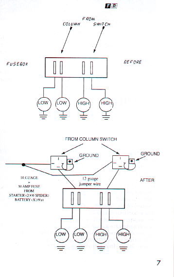
This next step involves installing headlight relays. There are three reasons I like installing headlight relays. One is because there are so many connectors that current must pass through , it would be extremely time consuming to replace everyone of them. Second is to save wear on your headlight and column switches. And third is because I think H4 headlights require more than 12 volts in order for them to perform at their best. If I remember correctly after replacing the 3 prong connectors, the grounds, the connectors at the fusebox, power went from 8 volts to around 12.3 volts and the H4 headlights were still dim. When purchasing headlight relays, stick with a good brand like Hella or Bosch. Don't waste your money on those cheap $3.00 relays. They are junk and I can speak from experience.

On the 124/2000 Spiders, I mounted the headlight and foglight relays behind the instrument cluster (actually behind the fuelgage). Be sure not to place them to far to the right or they will be behind the speedometer and the instrument panel may not fit. I did not take any photos but here is how I did it. Drop the fusebox and drill up through the framerail that runs above the fusebox. Then use some 1.5" long #10 screws and nuts to hold the relays. By mounting the relays here you can simply unplug the wire from the fuse box and hook it to the relay. Then by using a 12 guage jumper wire, run the wire from the relay back to the fusebox where the original wire came from. Then the circuit splits through two separate fuses, then one wire goes to the left headlight and the other one goes to the right headlight (low or high beam which ever the case may be). The main supply wire is a 12 guage wire + a 30 amp in-line fuse which is connected to the starter. Since the fusebox is the last point before power reaches the headlights, placing the relays here will ensure that they will be recieving full power. To make things easier, I used blue wire for the high beams, green wire for the low beams and yellow for the foglights.

Here's a tip. You are running foglights you can easily get your feed wire from the fusebox. You will notice that AFTER the fuse, there is a second unused connector. If you wish your foglights to run off the low beams, connect the feed wire to one of the low beam connectors. Since my auxillary lights are so bright I do not run them against oncoming traffic so I connected mine to one of the high beam connectors. So when I need maximum lighting, I flip on my high beams and my auxillary lights come on. Since OEM auxillary lights do not work on high beams, I assume my method is against the law. I don't know what that's all about. Most OEM auxillary lights are pointed so low I don't see what the deal is.

On my X 1/9 I mounted the relays behind the fusebox on the bulkhead. It may be easier to crimp an extention wire to the wire coming from the fusebox so you don't have to unwravle the black tape which is wrapped with other wires. Use a butt connector and a 12 guage wire to make the extention. You can connect the main supply wire to the relay directly from the battery on this model. Actually I got lazy and only mounted one relay for the low beams so far. But I do have two relays on the Spider.

All countries have different law regarding headlights. In the United States, both low and high beam headlights cannot burn at the same time (I think this is an accurate statement). With that in mind you can use a single 10 guage wire from the starter or battery and then split the wire into two more 10 guage wires using an 8 guage connector to connect the three. Twist the two 10 guage wires together and insert them into the 8 guage butt connector. For the single wire, strip the wire back about 1/2" , twist and bend it so that the wire appears to be twice as thick as what it should be. This will mimic a thicker wire and ensure a snug fit when you crimp it.

When I relocated my headlight relays from the steering column support bracket to behind the instrument cluster, this time I used 12 AWG wire for both the wire coming from the battery and the feed wire going back to the fusebox. I originally suggested using 10 AWG for the main wire but LittleFuse sells 30amp fuse holders connected to 12 AWG wire. The original headlight wiring is rated for no more than 16 amps so 12 AWG wire should be sufficient.

I haven't had any problems with using a single feed wire on the Spider. If for some reason use should blow the 30 amp fuse frequently on the main supply wire, install a second wire for the high beams. I thought at first that toggling between low and high beams would cause a surge and blow a fuse , but so far so good. Other countries may allow the low beams to burn when the high beams are on, if this is the case, then install two 10 guage wires from the starter or battery.

When running auxillary lights, be sure to fuse each foglight. I used 14 AWG wire and two 7.5 amp fuses.

Here are a list of problems and potential solutions:

Starter problems:

Starter does not turn/no click present.
Check the wire going to the solenoid. Sometimes this wire comes loose, breaks or becomes corroded. The best solution is to just install a new connector.

Starter does not turn but a "click" is present (mostly an intermittant problem).
I had this problem on my 80 Spider. The reason this happens is because there is not enough voltage being supplied from the ignition switch to operate the solenoid. This problem is more apparant when the headlights and other circuits are turn on when trying to start the car. My 80 Spider has had this problem since I bought it six years ago. About three years ago I purchased a low voltage relay (which requires a minimum of four volts) from Maduko which was invented to cure this problem. The problem got worse over time, so I decided to stop procrastinating and install the relay. Since then the car has never failed to start. Makuko as since bit the dust. The only supplier that I know of that supplies this relays is Caribou imports which I was told by ED was the original supplier. To be honest I see no reason why you cannot use a 30 amp foglight relay. All your doing is supplying enough power to engage the solenoid.

Starter drags:
Most common is a weak battery. If the battery gives an output of more than 12 volts the brushes and/or bearings inside the starter or worn. Although the factory shop manual on the Spiders says to drop the starter from between the steering linkage, I found that method impossible. A much easier method is to remove the alternator and remove it that way. I had the radiator out at the time so it may be nessessary to do so but first try removing the windshield washer tank (F.I. models).

Other points worth mentioning:
1) Connectors on ignition coil. Replace the control module on the 2000 Spiders if original.
2) Fuel injector grounds. Found on air intake plenium on 2000 Spiders, cam cover on X 1/9s.

If the battery light still glows at some point or another, I wouldn't worry too much about it. I installed a voltmeter guage directly to the ignition switch and found that no matter how many circuits are turned on, the alternator is still producing over 14 volts. The voltmeter guage on X 1/9s is useless the way it is wired. It can be re-wired directly to the ignition switch for a true reading.

As I said before, the terminals inside the car are usually not the problem. I went to all the trouble to install new terminals on the fusebox on my 80 Spider. I also polished the fuse holders with a dremel tool attachment. I saw no noticeable difference afterwards. It is a good idea to install new fuses. Some people may dispute me on this but fuses are just like bulbs. As they age they will eventually blow for no apparant reason. My 80 Fiat Spider once left me stranded because of this. I only had the car for about 3 months when the fuse to my fuelpump decided to blow one night while I was in town. As most of you know, the fuse on fuel injected models is located in a separate fuse holder. I didn't know where it was located and had to call a towtruck. The next day after calling a friend I finally found it. I replaced the fuse and it has been there for over five years.

Fuelpump fuse holder:
While I am on the subject of the in-line fuelpump fuse holder, I had a little mishap on the way to Fiat Freakout 2000. About 170 miles into the trip, the car just died. To make a long story short, the fuse holder melted due to age. Bakelight plastic doesn't last forever. Instead of simply replacing the fuel holder, I thought of a neat trick. This trick only works on Spiders without power windows (like they actually work worth a dime to begin with). Fiat intregated the power window circuits into the fusebox which use the two leftmost fuse holders, but without power windows, they are basically just spare fuse holders. Drop the fusebox and unplug any wires you see connected to these connectors. I know there is a red wire and possible a pink wire. I can't remember if these wires have power on them or not. To be on the safe side, wrap electrical tape around the connectors.

Unplug the two brown/white wires leading to and from the fuse holder. These wires are long enough to reach to the fusebox. Now just plug each wire onto the opposite ends of the leftmost fuse holder. If you haven't robbed the 16amp fuse by now for something else, be sure to replace it with an 8amp fuse. And be sure the wires are on the opposite side of the fuse holder to make sure the circuit is protected. Just to be on the safe side, remove the fuse to make sure the engine won't run. Now the fuelpump fuse is where it belongs, in the fusebox and not up underneath the dashboard.

Cigarette lighter fix:
OK, so it's not cool to smoke in the 21st century. Well I do so sue me! If you have to press in on the cigarette lighter element until it get's hot or it doesn't work here's how to fix it. You'll probably have to remove the radio console to do this. You will find two small tabs that hold the end of the element in place while it's heating up. When the element get's hot enough, the tabs expand, they release the element and your ready to light up. These tabs get weak overtime. The trick is to bend them inward SLIGHTLY with a flathead screwdriver. Be sure to disconnect the connector first.

Slow signal/hazzard lights:
Even after you have done allot of the steps I've mentioned, if your turn signals/hazzard lights flash very slow (like once every two seconds), the problem is most likely the flasher unit itself.

Radio trick:
As you know there is no position on the ignition switch for the radio. It's not a good idea to leave the switch in the ON position without the car running if you want to listen to the radio while sitting. This can damage the ignition system. I wish I could take credit for this since it's such a great idea but I cannot. I read it in a FLU Ricambi issue. Most people by now have disconnected the door chime. You can use the + wire going to the chime to power the radio. So when you insert the key into the ignition switch, the radio automatically comes on. This wire is fused on the 2000 Spiders but to be on the same side, install an in-line fuse before the radio.

Spider wiring diagrams:

UPDATE!!
Finally! The day has come. 124/2000 Spider Wiring diagrams are now available for downloading in ZIP format! Although I didn't care to distribute these diagrams via email, it was a hassle. But I did it regardless for the love of the car. Thanks goes out to fellow 124 Spider owner Chris Alemany for providing the space for these diagrams on his server.

I scanned these diagrams at a high resolution so they wouldn't look blocky when printed. They are quite large so grab a Pepsi or smoke while they download if using a phone modem. You will need something such as PaintShop Pro or similiar graphics program in order to print each JPG to a single sheet of paper. It won't work using Internet Explorer. Or at least I've never been able to get it to work using IE.

I'm trying to obtain wiring diagrams for other models. So far these are all I have. I've heard there isn't much difference if all between 74 to 76 in the wiring so it's possible the 76 diagrams will work with earlier models but I can't swear to this. I would appreciate any information as to where the 76 diagrams will work on earlier models. Please let me know so I can mention this on my webpage for other owners. Thanks.

If you are downloading diagrams for the 79 or 80 Spider, you will notice the heading of some diagrams that will say 81 to 82. There is no difference in the wiring as far as I am concerned but one owner reported that the fuses were in a different order in the fusebox on his 79 model. But these cars have been around for so long, who knows if a PO did this. His is the only case I have heard of. And the only difference between the carburated and fuel injected 2000 models is fuel delivery system. The carburated version has a single page related to components related to the carb which the fuel injection version doesn't have and vice versa.

1976 124 Spider
1977 124 Spider
1978 124 Spider
1979-80 2000 Spider (carburated)
1980-82 2000 Spider (fuel injected)

Here are some diagrams for the Fiat X 1/9. I have not studied these to see what year they correspond to. They are linked from another page.

Fiat X 1/9

If you happen to have any good diagrams (circuits broken down on several pages, no single page Haynes diagrams) for other models not listed here please scan them at a high resolution and email them to me. If you don't have access to a scanner, how about photocopy them and send them to me through the mail. This will help other Spider owner's keep their cars on the road.

I hope this page is of some help to you. If you have any questions, feel free to email me. But remember if you wire up your relays wrong and smoke your wiring, don't ask me what you did wrong.


Back to Homepage