|
Author: Matt Webb
Email: MattWebb502@yahoo.com
Date: 05/01/2006
Subject: Fiat 124, replacing
fuse block with an ATO style.
Resources: first hand
experience.
|
Parts required
From www.mcmelectronics.com
2x MCM p/n 28-1185,
five gang ATO fuse block
1x MCM p/n 28-6073, 0.250 flag disconnects,
bag of 100
1x MCM p/n 28-6092, flag disconnect sleeves, bag of 100
some heat shrink tube in various sizes/etc.
some 10 and 12 AWG stranded wire
solder,
soldering iron
epoxy
1/8" steel plate
Crimpers,
crimp connectors
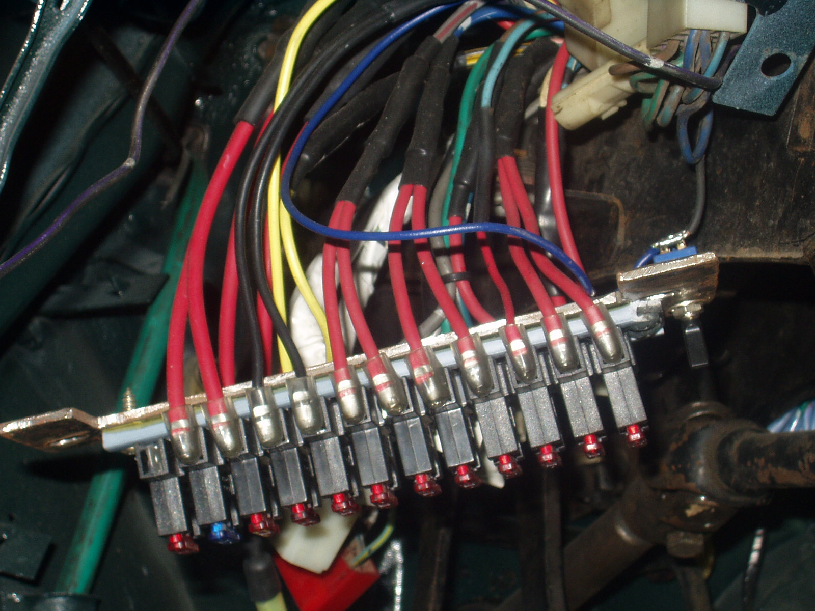
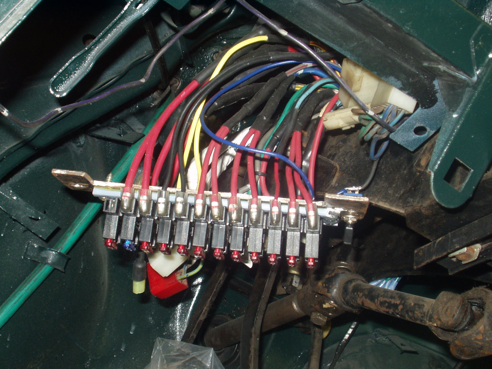
 In the pic below you can see the new fuse block mounted in place as well as the adaptor plate that must be fabricated out of 1/8" steel.
About the Adapter Bracket
Because the new fuse block does not have rear exit connectors the adaptor must be made to provide a small gap along the top edge to allow the wires to safely pass through without risk of chafing.
In the pic above you can see where the bracket was notched out on the lower left hand corner this is to provide clearance for the hood release lever. so keep things tight to ensure no problems here.
Sorry I don't have any specifics on the bracket dimensions/etc. Just get under there and make measurements. not too hard to fab this up. Most important thing is keeping clearance for the hood release!
The fuse blocks
What you see in the picture is actually two fuse blocks
butted together end to end. Each block consists of five fuse sockets and mount
points on either side.
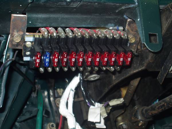
The stock setup in my 124 had 9 fuses IIRC. . I happened to
have an extra block, so I used a couple extra sockets and ended up with 12
sockets. 1 spare, 1 added circuit for my fuel pump and electronic ignition, and
I split one of the stock circuits up into two for easier troubleshooting in the
future. The fuses in place aren't necessarily the values that will be used. . they were put in place to take pictures.
Slight modification required to get them looking like they
do here. attention to detail here will give you a nice tight fuse block ---
when you first get them the sockets are all loose and cheap feeling, but
they're nice.Hard to explain this really, you need to have them in your
hands to really understand what has to be done.
Wiring it up
This is no place to go practicing your soldering skills. If
you're good, go for it. If you aren't so good with an iron then I wouldn't go
messing with it. you're just asking for problems. Practice elsewhere first.
Basically you want to let the old fuseblock hang in place as
you move one wire at a time from it to the same location on the new fuseblock.Because the stock block has rear exit connectors you will
have to extend all of the old wires slightly. I added in about 3" of new wire
to each one. Also with the old block some of the spots are actually junction
points for more than 1 wire. I just removed these points, soldered the wires
together and soldered my extension pigtails to them. don't forget the
heatshrink tubing.
It is helpful to make the extension wire complete with the
flag disconnect and attach it to the new block first. this way you can help
minimize stress at the connectors. otherwise you could end up with a wire that
must be twisted in order to connect it to the fuseblock. NOT a good thing,
especially with the short runs of heavy gauge wires and the flag disconnects.
In my case I didn't have the best of luck getting these flag
disconnects to crimp properly. no problem though because I intended to crimp
and solder them. If soldering them make sure the connectors face upward to
prevent the solder from running into and clogging them.When soldering to the new extension wires to the existing
harness wires I used crimp connectors make sure you have real good
connectors and, more importantly, HIGH QUALITY CRIMPERS. the flimsy piece of
junk crimpers are a no no. Go to Lowes or Home Depot and get a pair of the
Klein crimpers (NOT the GB ones!) http://www.service.kleintools.com/Marketing/Catalog_Imagery/1005_icon.jpg I slit the insulation of the crimp connectors, crimped well,
followed up with solder – provides a better bond and keeps moisture OUT. Don't forget to put that heat shrink tube in place before you solder / crimp!
More pics
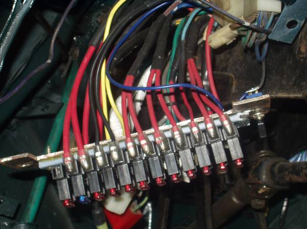
Notice in these shots you can see where a few of the flag
disconnects are skewed / stressed. try to avoid this as much as possible! The switch you see is a manual over ride for radiator fan
relay control.


 In the pic below you can see the new fuse block mounted in place as well as the adaptor plate that must be fabricated out of 1/8" steel.