 |
Author: Richard Ridge Email: ridgevitale@mac.com Subject: Replacing the Front Control Arms - Fiat Spider Resources: first hand experience. |
|---|
NOTE: This document is a combination of referring to the factory manual, and actually performing the work on my 1978 Spider. There may be a few slight differences depending on the year of your car.
REMOVAL
The shock absorbers will need to be removed in step 9.It is easier if you start by disconnecting the top of the shock before jacking up the car. I had to use an acetylene torch to cut the nut off the top because it was rusted into place (I was replacing the shocks anyways). Good luck if you don’t have a torch! If you do plan to use a torch, have a couple wet rags handy because most likely the rubber bushing on the shock will catch fire.- Loosen the lug nuts on the front wheels.
- Jack up the car and put jack stands under the crossmember.
- Remove the wheels.
- Unbolt the brake caliper and use some wire (such as a coat hanger) to hang the caliper out of the way. Be careful not to stress the brake hose.
- Remove the 2 bolts holding the brake disc, then remove the disc.
- Mark the hub so that you know which side it came from (driver or passenger side).
- Remove the bearing cap from the hub, then remove the nut and washer from the hub.
- The hub can now be pulled off.Be careful not to let the front bearing fall to the ground.Also be careful not to damage the bearings or bearing races during removal.
Be sure to keep the hub and bearings together as a set. They should go right back where they came from. Also the brake discs should not be mixed up.
- Unbolt the bottom of the shock absorber and remove the shock.
- Disconnect the tie rod from the steering knuckle. You will need a tool to do so.
- Unbolt the sway bar from the lower control arm.
- Install a spring compressor and compress the spring.
- Once the spring is loose (no tension on the lower control arm) you can remove the pivot bolt from the upper control arm. The upper control arm should now be loose from the chassis.
- NOTE: If there is still some residual spring tension, then put a floor jack under the ball joint and jack up the lower control arm a little. Then remove the pivot bolt.
- Tilt the steering knuckle down until it rests on the floor. Remove the spring.
- After the spring is removed, immediately remove the spring compressor.Never leave a spring in a compressed state.
- Unbolt the lower control arm from the crossmember.
IMPORTANT: there may be some spacers (shims) between the pivot bar and the
crossmember. Do not remove the shims, they are for setting the wheel alignment.
DONE! Repeat steps 5-17 for the other side of the car. Put a mark on the steering knuckles so that you know to which side they belong.
You can now remove the control arms from the steering knuckles. Use the same tool that you used for removing the tie rod in step 11.
Remove the grease seal from the back of the hubs, then remove the inner wheel bearing. Be careful to keep the bearings and hubs together! The bearings must go back to the same hub from which they were removed. The hubs must go back to the same spindle from which they were removed.
Clean the wheel bearings with mineral spirits or turpentine. Dry thoroughly. Also clean the inside of the hubs with a rag dipped in solvent. Clean the spindles on the steering knuckles.
Now is a good time to carefully inspect the crossmember for cracks, rust damage, etc. It is relatively easy to replace the crossmember now that all the suspension is removed. Better to do it now then after everything is back together!
INSTALLATION
IMPORTANT: Do not tighten the rubber bushings on the pivot pins until told to do so! The rubber bushings must be tightened only after everything is back together and the car is loaded with weight to simulate the normal driving height. If you tighten them in advance, the rubber will become twisted after the car is dropped and loaded with weight. This will cause premature failure of the bushings.- The upper control arm must slide into position during step 8, so start by cleaning the shock tower where the upper control arm attaches. This will make it easier to slide the upper control arm into position.
- Attach both control arms to the steering knuckle.Torque the nuts to 72 ft-lbs. You can use a crowfoot wrench on your torque wrench. Don’t worry about the small resulting error in torque.
- Here is a picture of a crowfoot wrench:
- Attach the lower control arm to the crossmember.Torque the nuts to 43 ft-lbs. Let theassembly tilt down until it rests on the ground.
- Use a spring compressor to compress the spring, then place the pad on top of the spring.Rotate the pad until it properly butts-up against the end of the spring.
- There is a shoulder on the lower control arm that the end of the spring should also butt-up against. Orient the spring so that the end of the spring is in the proper position, then insert the spring into the shock tower.
- Push the bottom of the spring into place on the lower control arm.Make sure the end of the spring is going to be up against the shoulder on the lower control arm.
- Now grab the steering knuckle and rotate everything up into position, making sure the spring is in the proper position on the lower control arm.
- See if you can slide the upper control arm into position on the shock tower.To make iteasier to slide, spit on your finger and rub it on the shock tower. (hey, it works!)
If necessary, put a floor jack under the ball joint and jack up the lower control arm(compressing the spring) until you can get the upper control arm into place.
Insert the pivot bolt to secure the upper control arm and then lower the jack. Do not torque the nut on the pivot bolt!
- Remove the spring compressor.
- Install the shock absorber.On my car the top of the shock did not stick up high enough to install the upper nut. I had to bolt the bottom of the shock into place, then wait until the car was lowered before I could secure the top of the shock. You can torque the lower nut to 43 ft-lbs at this time.
- Attach the sway bar. Torque the nuts to 14 ft-lbs.
- Attach the tie rod to the steering knuckle. Torque the nut to 25 ft-lbs.
- Attach the front hub:
- Pack the bearings with new grease
- Put some grease inside the hub (on the bearing races and in the middle of the hub)
- Install the inner bearing into the hub
- Install a new grease seal (you can use a piece of wood to tap it into place)
- Grease the spindle
- Install the hub onto the spindle
- Install the outer bearing, washer, and a new nut
- Torque the nut to 14.5 ft-lbs while rotating the hub in both directions
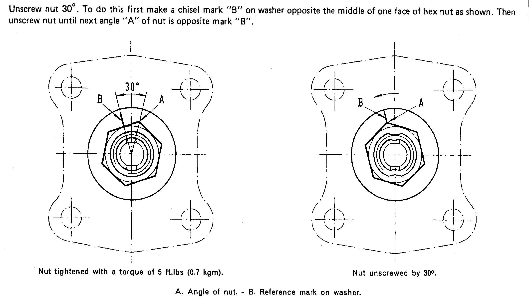
- Loosen the nut and then re-torque to 5 ft-lbs
- Unscrew the nut 30° as follows:
- Crimp the nut to lock it into place (you can stake it using a chisel)
- Pack some grease into the bearing cap and then install it onto the hub
- Attach the brake disc, the brake caliper, and the wheel.
- Repeat steps 1-14 for the other side of the car.
- Lower the car.To provide clearance to work, put a cinderblock under each wheel (all four wheels).
- NOTE: Lower the car until the rubber bushing at the top of the shock absorber just begins to contact the top of the shock tower. Now move the top of the shock around until the rubber bushing is properly centered into position. If it is hard to move, then raise the car a little. After they are in position, lower the car and install the nuts onto the top of the shocks. Torque to 11 ft-lbs.
- Load the car with sufficient weight to simulate normal driving (the manual calls for 2 people plus 130lbs of luggage).
- Torque the upper control arm pivot bolt to 65 ft-lbs.
- Torque the lower control arm bushings to 72 ft-lbs. Done!
OK, after you drive the car around the block a couple of times to admire your work, take it in and get a front-end alignment!