Trouble Shooting the Ignition Switch
on the Fiat Spider
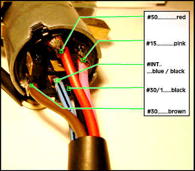
Additional Pictures
of the Ignition Switch:
Chris Courter's article on Ignition Switch Repair HERE
Photo of rear of switch with color information HERE
Introduction:
The ignition switch
looks complicated, but there are really onlyfive wires involved
in the circuit. They are arranged in just two sets. Some model
spiders have a warning light that will illuminate when the key
is in the ignition. These wires are not part of the switch circuitand
can be serviced separately.
Most problems with switches
are the result of burnt contactspreventing the connections from
being made internally. With simple hand tools and a small drill,
you can disassemble the switch and clean the internal contacts
and restore the switch to normal operation. Instruction for this
procedure is found HERE.
Left Side:
First is the Bl/Bk -Brn-Red
Operation Explanation
Position 1 (Off) None of the wires are connected
Position 2 (Run) Brown is connected to black
Red is not connected
Position 3 (Start) Brown and Red (starter solenoid) are
connected to black
Right Side:
Blk-Pink set
Operation Explanation
Position 1 (Off) None of the wires are connected
Position 2 (Run) Pink and Black are connected
Position 3 (Start) Pink and Black are connected
Summary:
Quite simply when the switch is off, no wires are connected.
When the switch is in the Run position Blue/Black is connected
to the Brown power lead, and the Pink wire is connected to the
Black wire. When the switch is in the Start position the only
change is that the Red starter solenoid lead is added to the
brown wire connection.
Symptoms of a Bad Switch:
Loss of connectivity will cause intermittent issues like sudden
engine dying or lights that won't stay on. Sometimes you can
wiggle the wires gently at the back of the switch to get you
home if this is the problem.
Spade Connectors:
Some model cars had spade connectors that cause problems. Early
models had screw on connectors. Middle year cars had push on
connectors. Most later year models had soldered pigtails to connect
the wires to the switch. I highly recommend that if your car
has spade connectors(push on), then remove the switch from the
column and carefully solder the wires to the back of the switch.
Replacement Switches
Polish replacement switches can be retrofitted, but the new replacement
switches are not of the same quality as the OEM versions. OEM
Switches are highly sought after by knowledgeable owners. With
a little time and patience, it is possible to repair most OEM
switches. Instructions for this procedure are HERE.
Relay Modification:
Now that you understand
the "secret" of the switch, you can help the switch
to last longer by removing the high current that caused the switch
to malfunction in the first place.
All electrical current for
the vehicle (with the exception of the starter motor and the
alternator charging current) must pass through the ignition switch.
With a little thought, you can use two relays to handle the current
switching making your precious starter switch last indefinitely.
This will be a topic for a future FAQ (or why not write it yourself
and submit it to MIRA for publication?).
|